Region modeling is an alternate method of creating two-dimensional (2D) geometry quickly and
easily. Region Modeling can be used ingeniously in both engineering and architectural drawings.
It is very different from conventional geometric construction because of the use of Boolean
operations. The Boolean operations (union, subtraction and intersection) allow entities to be
joined together into a single entity or subtracted from each other. Once the region is created,
CADopia automatically calculates its mass properties. The properties available include:
- Area
- Perimeter
- Centroid
- Moments of Inertia
- Product of Inertia
- Radii of Gyration
- Principal Moments and principal axes about the centroid
You can use the Region command to convert an entity that forms a closed shape into a 2D Region
entity. Region command can combine all entities of any closed loop – such as closed Polylines,
Circles, Ellipses, and closed Splines – into one region entity. Then, you use Boolean operations
to create new shapes or modify existing shapes. For example, you can subtract a circle from a given
shape to define a hole.
After creating a Region, there is little visual difference on screen except when the original
entity had a width, thickness, or line weight. This information is lost when you create a region
from such entities.
A Region is a 2D planar surface, not simply a boundary contour. If the source entities of the
Region are hatched, the Hatch loses associativity to the boundary. You must re-apply the Hatch
to the Region entity. You can also create Regions with the AreaBoundary command by setting the
resulting entity type for boundaries to Region.
The concepts of union, intersection and subtraction Boolean operations are explained below
using a simple rectangle and a circle.
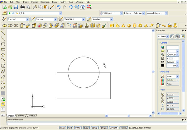
Union
Use the union command to join a group of entities into one region. Selecting the circle and
rectangle creates the region shown above.
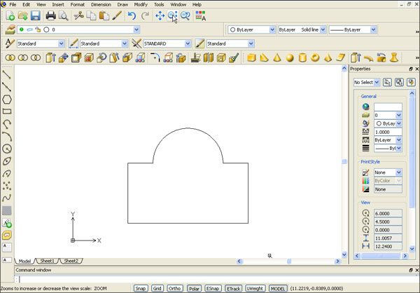
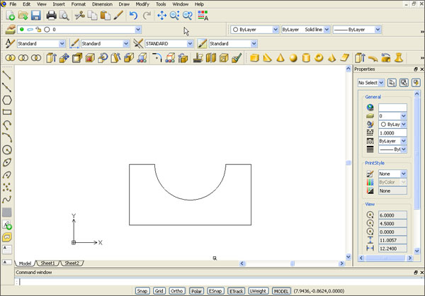
Subtract
Use the subtract command to subtract an entity or a number of entities from a source object.
The result of subtracting a circle from a rectangle is shown below.
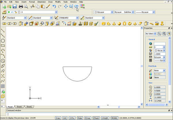
Intersect
Use this command to produce the region from the intersection of two or more entities.
The result of intersecting the rectangle and circle is shown below.
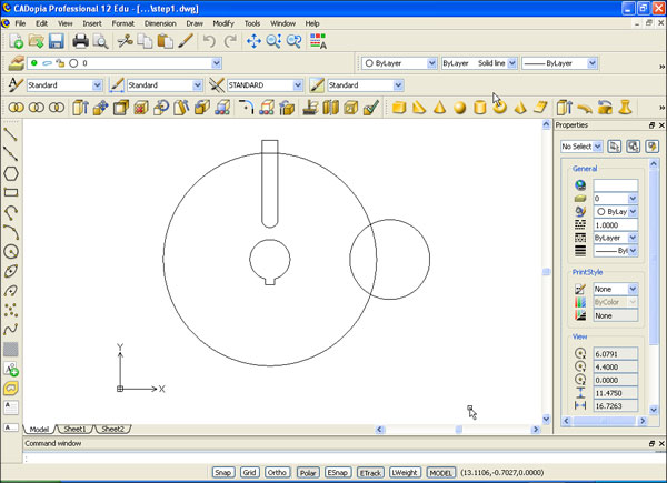
Open the drawing (Download the example dwg files)step1.dwg.
It shows the basic shapes that will be used to create the governor drawing using Region Modeling.
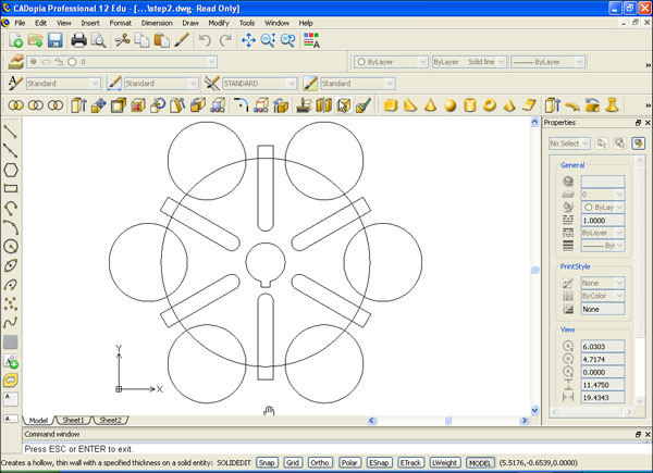
Use the array command to create a circular array 60 degrees apart to get the results drawing as shown below:
Convert the entities into region by selecting all the entities. You will not notice any visual
difference in the drawing once the entities are converted to Regions. But if you check the entity
type in the property dialog box, the type of the entities will appear as a Region.
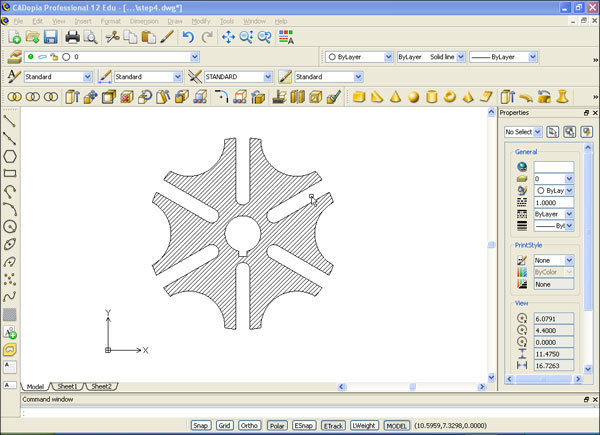
Next, we do the Boolean operations to create the final shape.
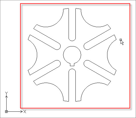
Type subtract at the command line. Select the larger circle as the source object from which to
subtract. Select all remaining entities as the items to be subtracted. The resulting shape is
shown below:
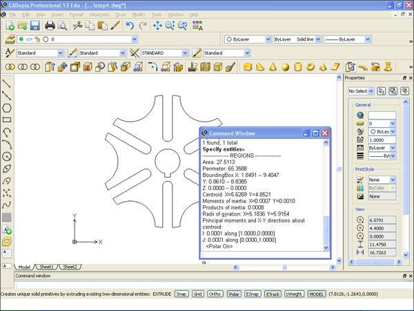
To determine the mass properties, type massprop and select the shape.
The mass properties appear in a separate window as shown below.
Once the Region is created, you can use it as any other regular entity. You can apply a hatch pattern and dimensions to a Region, for example.
We hope you have found this article useful. If you have questions or comments, please send them to support@cadopia.com.