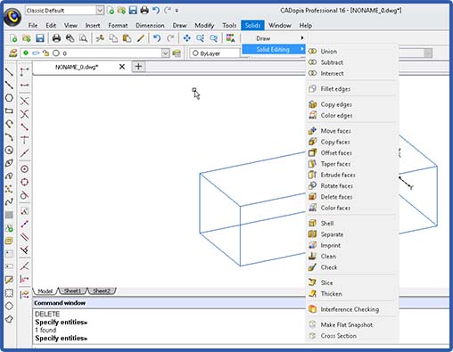
CADopia provides a number of editing features which you can use to edit solid models as per your requirements. Some of the editing features are:
- Union
- Subtract
- Intersect
- Section
- Slice
- Interference Checking
The following image shows CADopia’s Solid Modeling editing commands:
Fillets: Objects in the real world have well-rounded edges and corners. This can be created in a solid model by filleting the sharp edges of an object.

Before Filleting
After Filleting
You can assign colors to the edges and faces of the solid model. The colors assigned are used for rendering the solid model.
Edges and faces of a solid model can also be copied just like other entity types.
Additional editing operations available with faces include
- Move
- Offset
- Taper
- Extrude
- Rotate
- Delete
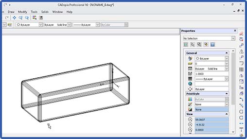
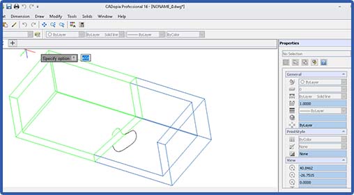
Sometimes, you need to hollow out a solid model to create an object with specified wall thickness. This can be accomplished in a single step using the shell command. To run the shell command, pick the 3D solid object and the face you want to open up, specify a shell offset distance. Shell operation is used frequently when designing the housing body, for example, the housing body of a computer.

Solid model after shell operation
Using the imprint command, you can imprint an object such as the logo
of your company on the body of a solid model.
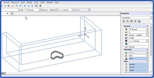
Solid model with the object to be imprinted
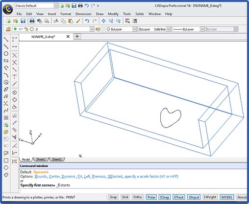
Solid model with imprinted object
There are two utility command available. Check checks the integrity of the solid model. Clean removes any redundant edges and faces in the solid model.
Slice command cuts the solid model into two parts. It is like running a butter knife through the solid model. This command can be useful in visualizing the internals of a complex solid. The section command is different in that the resulting section is a 2D planar object.
Sliced solid
Interference checking allows you to see if there is any interference between two solid objects in an assembly. Interference check highlights any common volume of interference detected. For example, if we move the two objects after the slice operation such that the two parts interfere, then run Check Interference to look for the interference volume, this is what you get:
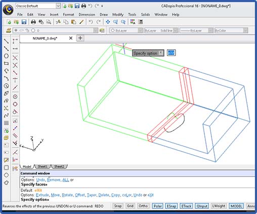
Image shows interfering volume
Finally, you can create sections from a solid model as required, just define the section plane with 3 points and the sectional view (in black lines) will be created for you as shown below:

Section created from a solid model
In future tutorials, we will provide step-by-step details for performing these operations using CADopia Professional Edition.